I thought I write about the system which is really not a biomedical instrumentation but it helps to manage asset by tracking equipment location with ease by locating them during periodic maintenance or in times of clinical needs for the patients where equipment are needed from the various available locations. It can also manage equipment utilization by tracking their utilization time by areas where repurchasing of asset could be kept to a minimum through maximized use of the equipment, etc.

In this write-up, the standard wireless-based network 802.11 tracking technology is taken as a model for the function of real-time locating. Where the current hospital or institution wi-fi network already exists within the premises, it actually helps reduce the cost of implementation by piggy-back onto the existing wi-fi infrastructure.
System Components
Consisting of an positioning engine that runs on an application software to deliver the visibility of the assets and together with a web accessed Vision software and the required number of RFID active tags, the system with its multiple complex algorithms measures and verifies equipment location, location status over a single unified infrastructure. Active RFID tags wirelessly communicate with the positioning engine to determine the location, etc.Methodology
There are many methodology for performing range calculation and they include the following:
- Angle of Arrival;
- Time of Arrival;
- Time Difference of Arrival (TDOA);
- Received Signal Strength (RSS);
- Time of Flight (ToF);
- Symmetrical Double Sided Two Way Ranging (SDS-TWR).
- Angle of Arrival
A method determining the direction of RF propagation from the RFID tag to the reader. The direction of the transmitted signal is being sensed by a direction sensitive antenna at the reader. The angle is determined by the angle made between the reader to the tag with that of the pre-defined direction, e.g., north. Most frequently two or more readers of know positions are using in the calculation of the location of the tag by adopting the simple triangulation association. This method of measurement often requires a complex set of between four (4) to 12 antenna arrays situated in a horizontal line at several cell site locations. The accuracy increases with the number of antenna arrays used. Resulting angle measurements are rather sensitive against multi-path propagation and is best suited for direct line-of-sight measurements between tags and readers.
- Time of Arrival (TOA)
TOA measures propagation delay of the RF signal between transmitted (tag) and the received (readers). Calculation of T1 - T0, the time lag of the departure of a signal from a source of the antenna to the reader; it is the time required for a signal to travel from the antenna to the reader.Multiplying the propagation time T1 - T0 by the propagation speed of the signal, the propagation delay can be converted into a distance between the tag and the reader.
To determine the position of the tag in a 2D plane, at least three (3) readers are required to take TOA measurements. To determine the tag position in 3D space, at least four (4) readers are required. The location of the tag can be seen as intersection of the circles. The accuracy of the method relies on the synchronization of the clock between the tag and the reader.
- Time Difference of Arrival (TDOA)
TDOA measures the difference in transmission times between the tag and the reader. Instead of relying on the intersection of the spheres, TDOA method measures the distance by the intersections of the parabolas. TOA records the time the antenna sends a signal to the readers. TDOA records the time the reader received the signal. Like TOA, TDOA also requires that each signal to be transmitted synchronously either at the same time or with some known delay between the signal transmission. TDOA requires 3 or 4 readers at know fixed locations to receive synchronously from the tag and record when the signal is received. The received time difference between the readers is sent to the location engine for calculation which uses an algorithm to provide the estimated position of the tag.
- Received Signal Strength Indication (RSSI)
This method requires at least three (3) access point to simultaneously tracked the location of the tag. The signal strength received from reader determines the location of the tag. The distance between the tag and the reader is determined by converting the value of the signal strength at the reader into a distance measurement based on the known signal output at the tag and on a particular path-loss model. RSSI requires a dense deployment of Access Points. An adequate underlying path-loss must be found for both non-line-of-sight and non-stationary environments. Estimated distance are somewhat unreliable.
- Time of Flight
- Round Trip Time (RTT)
To overcome the inherent difficulties of ToF, RTT provides a method whereby the ranging signal can be send and acknowledged, a process know as 'round tripping.' Using both data signal and acknowledgement mitigates against the problems with clock synchronization. RTT uses highly preditable hardware generated Acknowledgement packets where MAC processing time assumed to be equal on both nodes. Timestamps on the physical layer is used but not on application layer.
- Symmetric Double Sided Two Way Ranging (SDS-TWR)
This method overcomes the shortfall of the RTT by emplying a range signal sent out by the reader and an acknowledgement from the tag to cancel out the requirements for clock synchronization. It builds on that advantage by providing protection against multi-path propagation and noise by its Chirp Spread Spectrum Modulation technique. To eliminate the drift and offset of the clock, range measurements are taken by both the tags and the reader to provide two measurements that can then be averaged. The result is a reasonably accurate measurement of within 1 meter, even in the most challenging of environments.
RTLS Solutions
There are many visibility applications in RTLS namely Asset Management, Equipment Maintenance, Temperature and Humidity Monitoring, Patient & Staff Safety and Workflow & Resource Management. I will try to stress on two aspects of the visibility solutions as follows:
There are many visibility applications in RTLS namely Asset Management, Equipment Maintenance, Temperature and Humidity Monitoring, Patient & Staff Safety and Workflow & Resource Management. I will try to stress on two aspects of the visibility solutions as follows:
- Equipment Maintenance & Asset Management
historical data, etc. With an integrated maintenance management system, all status data and locations can be automatically populated from the RTLS.
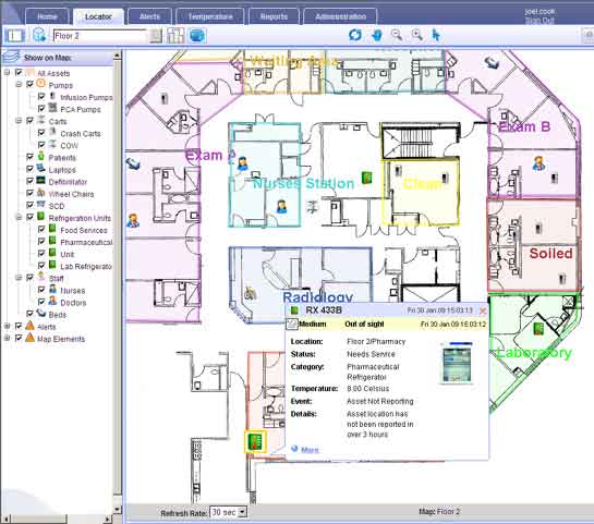
The location of each tagged equipment is displayed on the map of the institution in Vision software. It can display a complete building view to enable an at-one-glance view of the distribution of the assets.
Each tag periodically transmit signal to report their location over the wifi network. The location engine then collects the tag signal that are received by all the wi-fi access points that hears a tag. This information is used to determine the location of the tag.
The status of the equipment availability can be determined through several means, for example, an activation of a call button on the tag to indicate maintenance is required. Alert can also be designed to generate when equipment has been placed in an area demarcated as service or maintenance purposes.
- Patient and Staff Safety
 Staff members wearing WiFi tags can easily call for help by merely clicking a button on the tag. Security and other staff members are immediately notified of a duress event, identifying the staff member and location.
Patient such as elderly patients wearing tags with call button, can trigger panic or distress alerts. Notifications along with the patient's location are sent to staff and security.
Problems with RTLS
Poor Locating Determination2.4GHz, a relatively short wavelength used for wifi data transmission is susceptible to signal loss. For the purpose of discussion, we will take RSSI as the method for measuring the location of the tag. RSSI calculate the distance using the received signal strength between the access points as the basis for determining the location. The accuracy of the location will somehow depend on the continuity of the received RF signals. Due to the nature of the 2.4GHz, it is easily interrupted by moving assets especially human bodies that obstruct the path of the tags and APs. In a dynamic environment of a hospital, the result is consistently unpredictable signal loss, making meaningful and accurate determination of location impossible.
Triangulation
Wifi-based tracking system promoters incorrectly used triangular to describe how multiple APs determine the location of a tag. This misuse of the terminology vastly overstates the accuracy and the precision of wifi. Triangulation is the location of an unknown point by the formation of a triangle consisting of the unknown point and two known points in a triangle. The two known location APs must be able to measure the azimuth, or the angle within a reference plane, to a tag in order to make a triangle. Since wifi APs has no notion of azithmus or even that all three locations are in the same plane, how can APs triangulate anything? The fact of the matter is they can't.
This can potentially create problem for a hospital. Hospitals expect their WiFi tracking system to locate patients and equipment with clinically significant accuracy by the exact room and hallway. WiFi cannot reliably accomplish this function.
Some proprietary WiFi system can perform Cartesian coordinate estimation or other calculation such as time of flight, but this custom-engineered solutions are very expensive and the accuracy varied.
Noise
WiFi tags generate noise on the communication network. Excess RF noise reduces the effective range of every AP by up to 30%, interferring with and jamming up communication. Self calibrating WiFi technology that overcomes this problem is available but required significant additional cost.
Access Point Insufficient & Wrong Place
Hospital may think that they are saving money by building their tracking system on top of their existing WiFi network. They may soon face with considerable expense to upgrade their network. The placement of the APs sufficient for a typical hospital WiFi network just isn't dense enough to be used for tracking.
Reference: wirelessdesignmag.com; aeroscout website; ekahau website; nanotron technologies.
Reference: Ekahau Real-time locating system
No comments:
Post a Comment